Close
Our Products
    Filters
    Preferences
    Search

    Blade Assembly Procedure

    Introduction

    This document outlines the recommended procedure for installing blade assemblies in the propeller hub..


    Pre-Requisites

    Complete the following tasks before proceeding with this instruction:
    • Install Propeller hub (and mount kit) onto aircraft in accordance with applicable installation procedure. This is the recommended method, however in some cases operators may find it easier to assemble the blades to the hub before it is installed onto the aircraft.
    • Inspect Hub Bores for nicks and burrs.
    • Inspect each Blade Retention assembly for damage including threads on Retention Nut and Thrust Bearing elements.
    • Lubricate Hub assembly in accordance with Hub Lubrication Instruction.


    WARNING

    Ensure that aircraft power is turned off throughout this procedure.

    WARNING

    Proper installation of the blade assemblies is imperative for safe function of the propeller and ensuring the safety of the pilot. Ensure that all blade assembly checks contained within this instruction have been verified after the installation is complete.


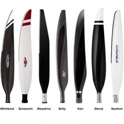
    Step 1  Blade Preparation

    • Ensure that all pre-requisites listed at the start of this instruction are completed.
    • The blade assemblies must be inspected for improper condition and lubricated in accordance with relevant instruction.

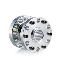
    Step 2  Hub Preparation

    • The hub assemblies must be inspected for improper condition and lubricated in accordance with relevant instruction.

    Note

    Park the pitch change mechanism at the coarse pitch limit for easier blade assembly.


    Step 1  Match Blade to Hub Port

    • Select one blade assembly and note the blade number marked.

    Note

    Each blade is marked with a single digit number on the cam plate, this indicates the hub port number associated for that blade, as configured when the propeller was statically balanced.

    • Orient the propeller hub with the corresponding hub port number face up.

    WARNING

    Ensure aircraft power is turned off before rotating propeller.


    Step 2  Locate Blade into Hub

        • Lower the blade assembly into the corresponding hub port and carefully align the cam-follower (blade) such that it locates into the slot of the pitch change slide (hub).

    Note

    By holding the blade retention nut with one hand while slightly twisting/moving the tip of the blade from side to side, the correct alignment is easily found. This can be felt when the blade feels restrained from further twisting at its base.


    Step 3  Seat Blade into Hub

          • Once the cam follower (blade) has correctly located into the pitch change slide (hub), gently force the blade downwards to partially seat the blade's alignment bearing into the lower bore of the hub.

    Note

    The blade and ferrule which it is attached to will slide partially into the hub, while the retention nut will remain seated on top of the hub threads.


    Step 4  Tighten Retention Nut

    • Use the assembly C spanner to tighten the retention nut untill it is fully seated.

    Attention

    Blade Assembly C-Spanner (AT-x)

    Note

    A combination of tightening then further seating of the blade into the hub (as per previous step) may be required if there is limited clearance between the ferrule nut and retention nut.

    Note

    While tightening retention nut, restrain the blade to prevent the assembly twisting or rotating inside the hub.

    Note

    While tightening retention nut, support the head of the C-Spanner to prevent it slipping out.

    Caution

    The retention nut should initially wind in smoothly by hand. Resistance may be met when the retention nut O-ring is fitted inside the hub (ensure O-ring is lubricated), however if resistance is met during initial tightening the blade is improperly seated or misaligned. Remove blade from hub and correct blade alignment before reattempting.

    •  Verify blade installation in accordance with Check Blade Assembly ahead.
     

    Step 1  Torque to 130%

    • Use Blade Assembly C-spanner to firmly tighten the blade retention nut to 130% of final torque value (refer Step 3). This will help to expel excess grease which may cause improper blade seating.

    Step 2  Back off Retention Nut

    • Loosen the retention nut a 1/4 turn.

    Step 3  Torque Rentention Nut

    • Re-tighten the retention nut to achieve specified pre-load torque setting by using a torque wrench applied perpendicular to the C-Spanner.

    Note

    If torque wrench is applied parallel to C-Spanner, a higher torque than that of the wrench will be applied. This torque may be calculated if the length of the wrench is known using the ratio of levers method, as used with a crow’s foot extension or torque adapter.

    Attention

    Torque Wrench (3/8-inch square drive)

    Propeller ModelPre-Load Torque
    AP332S 10.5Nm (8ft-lbs)
    AP3 12Nm
    AP4 15Nm (12ft-lbs)
    AP5 20Nm (15ft-lbs)

    Step 1  Blade Seating Check

    • Check top face of Retention nut is flush with hub face.

    Caution

    If Retention Nut is proud of hub this may indicate that excess grease packed in the Thrust-Bearing bore is causing the blade to seat improperly. Remove blade from hub and inspect grease applied in this region in accordance with lubrication instructions, remove excess.


    Step 2  Check Blade for Lateral Movement

    • Apply a moderate force fore-to-aft at the blade tip with one hand only and monitor the movement produced.
    • No movement should be evident between the blade assembly and hub (ignore the deflection due to the bending of the blade itself.

    Caution

    If blade assembly rocks within the hub this may indicate that excess grease was packed in the thrust-bearing bore and is causing the blade to seat improperly. Remove blade from hub and inspect grease applied in this region in accordance with Hub Lubrication Instruction. Remove excess grease as necessary.


    Step 3  Check Blade for Twisting Movement

    • Apply a moderate torque by twisting blade with one hand only and monitor the movement produced.
    • No movement should be evident between the blade and the ferrule into which it is mounted.

    Note

    A slight perceptible movement between the ferrule and the hub is acceptable, this is due to backlash in the pitch change mechanism.

    Note

    Some engines which incorporate a reduction gearbox (e.g Rotax) have a discernible backlash. Do not confuse this backlash with movement of the blade within the hub.


    Step 1  Check Retention Nut Plate Alignment

    • Check alignment between the two threaded holes in the hub and any two holes in the plate.


    Step 2  Align Retention Nut Plate Alignment

    • Further tightening of the retention nut in the hub may be required to achieve correct hole alignment. Up to 120% torque may be administered in this case.

    Step 2  Fit Retention Nut Plate

    • Secure retention plate with two philister-head screws (P0107) and torque to 2Nm (1.5ft-lbs).

    Attention

    Slotted Screwdriver, Torque 2.0Nm


    Step 4  Lockwire

    • Lockwire two screws. The single-wire method is acceptable.

    Attention

    Twist Pliers, 0.025” SS Lock-wire


    Parts Required

    ItemQtyPart #DescriptionImage
    1. 1  AB-xxx Airmaster Blade Assy   
    2. 1 AH-xxx Airmaster Hub Assy


    Tooling

    ItemQtyPart #DescriptionImage
    1. 1  AT-x  Blade Assembly Tool (C-Spanner)   
    2. 1 - Torque Wrench
    3. 1 - Lockwire Pliers


    Consumables

    ItemQtyPart #DescriptionImage
    1. as required   0.025” SS Lock-wire